Twin Coast Metrology’s optical metrology solutions can solve your unique inspection and quality control problems.

Twin Coast Metrology’s optical metrology solutions can solve your unique inspection and quality control problems.
Twin Coast Metrology’s software, SurfaceGage, excels at fully automated, camera based, optical metrology for manufacturing environments. SurfaceGage is at its core, photogrammetry software, that unifies single camera photogrammetry, white light/structured light scanners, and complex multi-camera, multi-projector measurement networks into one seamless software package.
In its simplest hardware configuration, a single camera, it is a like a photogrammetry system. Configure it with 2 cameras, and a video projector, it is a white light/structured light surface scanner. On the high end, it can support up to 16 cameras, FANUC industrial robots, Allen Bradley PLC’s, stepper and server motion control systems, stepper motion control systems, and fixed structured lights. This flexibility gives Twin Coast Metrology, great leeway for tailoring solutions to individual customer needs.
SurfaceGage has a state of the art bundle adjustment optimizer. The software can handle hundreds of thousand features, 500+ images, one to sixteen cameras, any focal length lens with full lens correction, self-calibration of cameras, automated data cleaning, uncertainty tracking, references systems, and temperature compensation, 100% automated, all at production rates.
SurfaceGage can calibrate video projectors, which allows projecting color maps directly on the part post measurement.
Calibrated video projector is also useful for accurately applying light patterns (dots, lines, grids, etc) on the part independent of the part position. For example, projecting dots of light at programmed locations enables high-speed surface measurements by skipping processing of features that are not of interest. A large point cloud is never created.


Twin Coast Metrology was approached by a customer that is manufacturing aircraft radomes. The existing process required that the radome and the radome tool be removed from the CNC mill, brought into the CMM room, temperature soaked, measured, then returned to the mill for processing. We delivered a system to measure the radome in place, using the utilizing the CNC mill’s motion system to support the measurement system. The delivered system performs profile measurements on both the solid surfaces and the honeycomb layers.
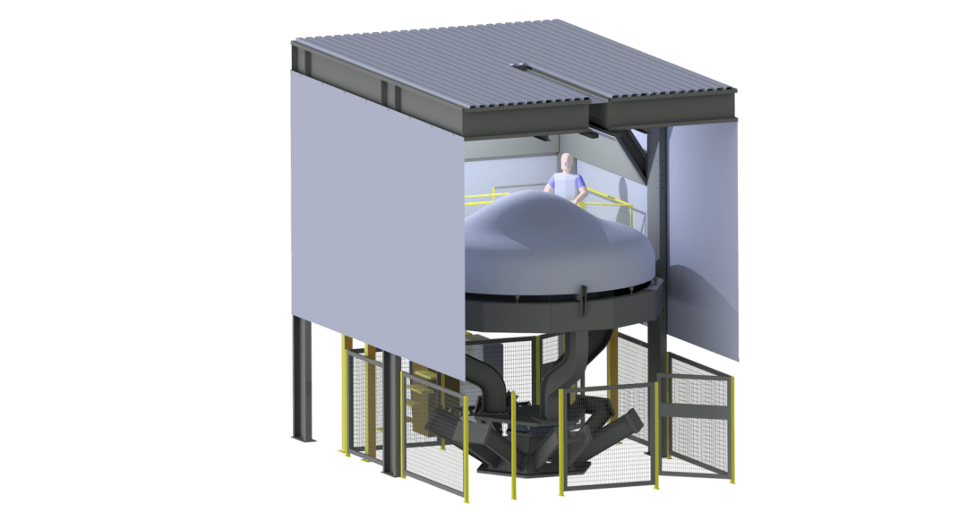
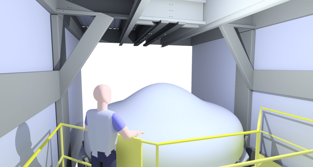
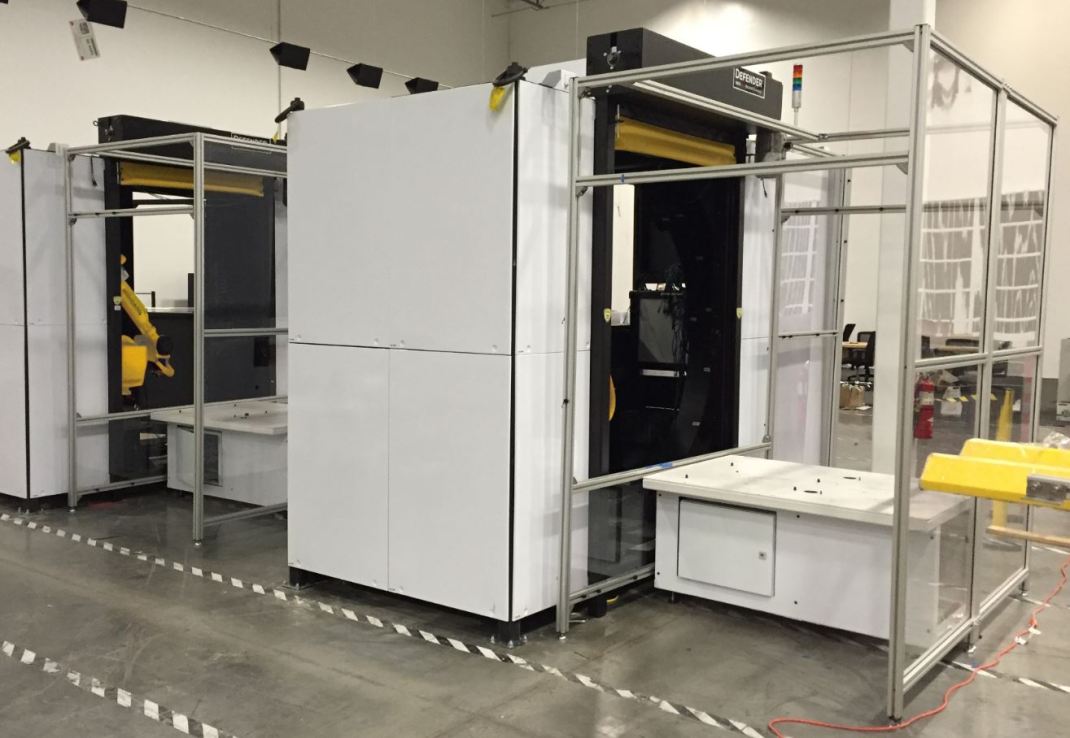
Our Hot Part Scanning technologies can robustly determine whether a forged part is compliant with manufacturer specifications immediately after forming or before cooling is complete.
System is capable of rapidly gathering data at part temperatures of up to 2100 °F
Use of optical technologies for measurement allows the system to keep these components thermally isolated from the floor environment. Active cooling reduces ambient temperature to safe, consistent levels.
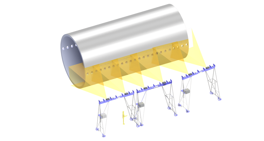
This system uses an array of 16 cameras and 8 projectors to rapidly gather 360° data.
Touchless optical measurement minimizes operator interaction with the part while gathering far more comprehensive data than traditional measurement techniques.


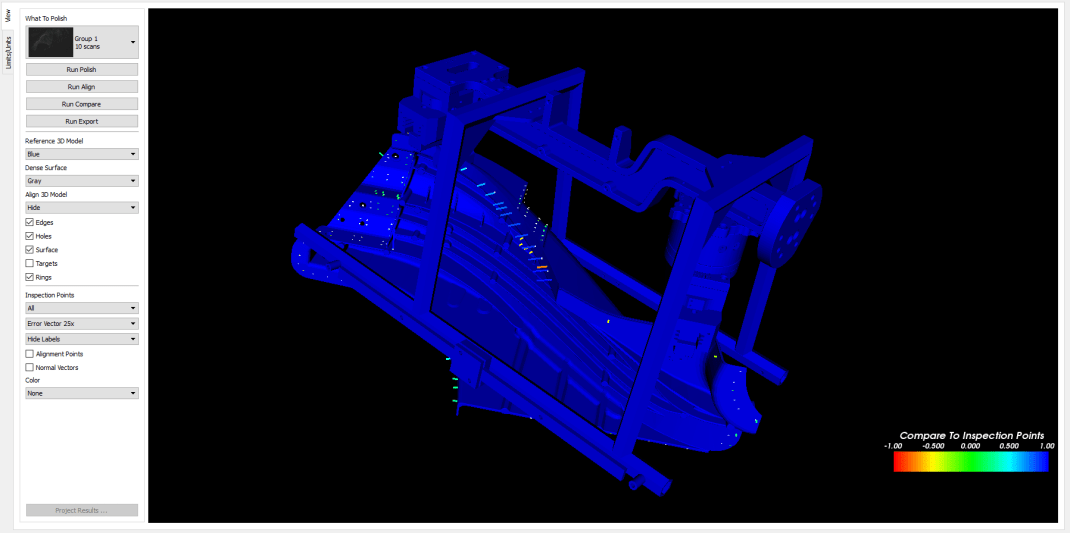
Results are reported quickly and comprehensively and are easy to understand. Green areas are well within specification, while violet areas represent underfill and red areas are excess material.

Our system was integrated into a fully automated, robotics driven cell, with robust PLC communication and results reporting.
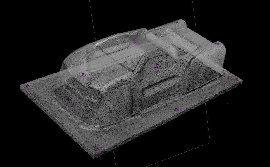
Inspection of a family of spun-formed components takes place from a single mouse click.

System achieves 0.015″ 2-sigma precision over a 12-foot (4 meter ) diameter.
As each part is inspected, the deviations from nominal (CAD) are projected directly on the part surface to illuminate pass/fail conditions. A digital copy of the color map is stored on the PC network.
Measurement results show machining yield from spun component.
Datums, tolerances, and inspection criteria are automatically applied to each part during runtime.
Hardware integrated into the work environment ensures that the parts can be bought off prior to the machining process. Any marginal or out-of-tolerance conditions can be identified and corrected before machining begins.
Cycle time including setup is reduced from hours to 15 minutes.
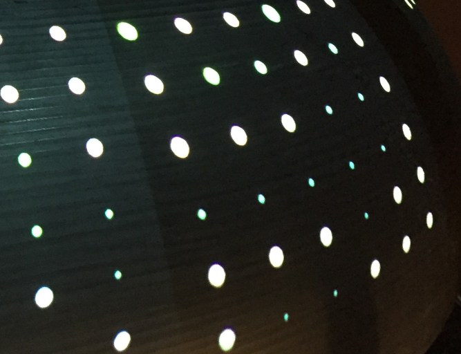
Twin Coast Metrology was approached by a customer with a large 20 x 40 foot cylindrically shaped fuselage segment. Their existing measurement methods would take upwards of 9 hours and required an expensive metrology specialist to collect data. We cut their measurement time down from 9 hours to 90 minutes with an easy to use interface that the mechanics could run themselves.
Developed over several years of field, production, and lab testing, CellGage is designed to determine exactly the honeycomb characteristics that customers require. There are generally three types of customer needs:
The hardware can be optimized for specific speed, accuracy, fields of view, cost, and portability. CellGage can do more inspections in less time compared to a CMM or laser tracker and is more accurate than other optical technologies such as white light scanners, structured light scanners, or laser line scanners.
CellGage has been used on a wide range of core colors, core sizes, and core materials, and has been used in a wide range of environments and part sizes. We have successfully measured aluminum honeycomb, Kevlar™ honeycomb, Nomex™ honeycomb, and flex core.


Twin Coast Metrology’s Casting Inspection Cell provides automotive cast part manufacturers the ability to measure hundreds of inspection points in seconds, slashing inspection times from hours to minutes. Rapid, in-line inspection supports 24/7 factory throughput.
With optical inspection tolerances as low 0.002” 2 sigma are achievable. Because of the casting inspection cell’s flexibility in measuring part sizes and shapes, future production lines can be easily adapted to the Cell.
The cell is completely adaptable for different parts down the line. Unique end of arm tools that connect to the robot can be designed for any part in the future.
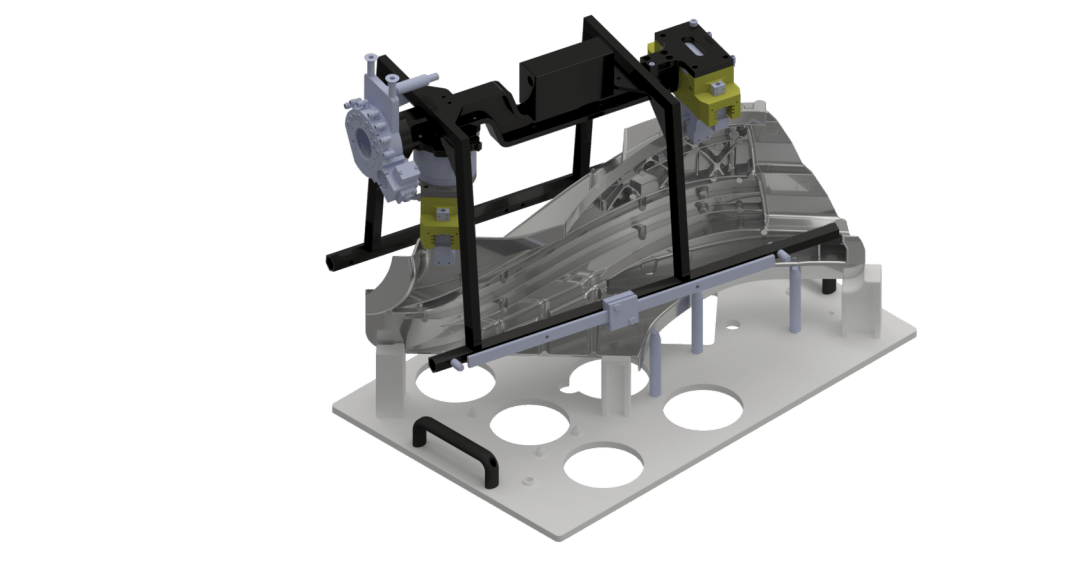
The cell is completely automated. An operator places a part in the fixture that is identified by a barcode or RFID chip to ensure the correct programs run for the correct parts. (Fixture shown below)

The Robot then comes out to interact with the custom end of arm tool and bring the part into the inspection cell.